Instrument Manager

Instrumentation and Loop Diagram Software
A new "data-centric" Instrument design and documentation system. Used for the automated production of instrumentation documents such as, Instrument Data Sheets, Loop Diagrams, Hook up Diagrams, Wiring /Terminal Strip diagrams, Instrument Index report, Bill of materials report, Cables Schedule report, Interconnection reports and many other documents. Live linking with AutoCAD P&ID software.
For Instrumentation and Control System Design Engineers
Instrumentation or Control system design engineers. These Engineers will typically be working with PLC or DCS based control systems for continuous processes. The instrumentation, I/O and connectivity for these controls systems requires a significant level of documentation (eg datasheets and loop diagrams), all of which can be efficiently produced with Instrument Manager.
Compatible with AutoCAD, BricsCAD, GstarCAD, and LusoCAD.
Intro: Design


Intro: Outputs and Reporting
Download brochure or videos
Request web demonstration, trial software, or sample projects
Features
Diagram Production

- Automated production of Loop Diagrams. (In AutoCAD Format)
- Automated production of Hook up Diagrams. (In AutoCAD Format)
- Automated production of Wiring /Terminal Strip diagrams (In AutoCAD Format)
Document Production

- Automated production of Instrument Data Sheets. (In MS-EXCEL Format)
- Automated production of Instrument Index report.
- Automated production of Bill of materials report.
- Automated production of Cables Schedule report.
- Automated production of wire interconnection lists.
- Automated production of conductor/core interconnection lists.
- Automated production of USER defined reports.
- Project Management and Revision tracking.
- Automated project drawing index list.
- Automated materials quantity summary report.
- Automated wire label / ferrule lists.
- Tag name duplication cross referencing report.
- Automated warnings summary.
- Revision comparison reports for all parts and connections.
Importing, Exporting, and Linking to AutoCAD P&ID
- An AutoCAD P&ID database (or other user "component" databases) can be live-linked with a minimum of effort allowing Instrument Manager to optionally access and modify data from the P&ID system.
- Exports and Imports are available to most common formats for ease of incorporation of vendor data and supply of customer data. Flat file and relational imports and exports are possible.
- Import and export directly from client instrument datasheets.
Database
- Database choices of MS Access and SQL Server.
- Tables and the structure of the tables is largely user definable.
- Multi-user system designed for concurrent engineering.
- Preliminary component, cable and enclosure information from Elecdes single line and cable block diagrams is instantly available for inclusion within your Instrument Manager database.
- Cable lists, components and enclosures within Instrument Manager can be instantly made available to Paneldes for modelling, interference analysis and cable and raceway routing and filling.
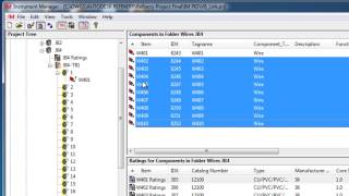
User Interface
- Users can work in a familiar drag and drop "explorer style" environment or in a tabular "spreadsheet style" environment with row and column copy/paste, search and replace, filter, sort and increment and many other "spreadsheet style" tools.
- Folders represent "containers" for instruments and other components.
- Use client datasheets as a form for your data entry.
User Management
- Users may be set up to be ADMINISTRATORS, USERS or VIEWERS. Administrators may be normal users that can manage other users and have advanced set-up options. Users manage the data and networking inside the databases, with the aim of producing output documents. Viewers can access the database as "read only".
Data Specifications
- Instrument data ratings and specifications are maintained in "per instrument type" tables and the contents of these tables are largely user definable.
- All components are "specification capable" and can have an instrument data sheet.
- User definable "WYSIWYG" instrument data sheets.
Template System
- Most output documents and diagrams are "template based" and as such, their appearance and data content are under user control. The templates are typically in AutoCAD format for diagrams, MS-EXCEL for instrument data sheets and MS Access for Reports.
Electrical Terminations and Links
- Association of components with their related areas, enclosures or similar can be done via drag and drop mechanisms which establish the link between the items. Electrical connections can also be done in this way. By dragging one or many conductors OR dragging whole cables on to a terminal strip (or an instrument) bulk terminations can be made.
- Loops and terminal strips are graphically displayed "WYSIWYG" as connections are made for those loops/ strips.
- Instruments and other catalog based devices can be pre-allocated cable types, automated cable naming, and terminations removing the need to create terminations manually.
- Imported components with valid catalog numbers can "adopt" cables and terminations as specified in their respective catalogs.
Event Log
- The Event Log records user nominated activities from user login/logout, to a component modification / deletion, to document printing or exporting. Events are logged with the activity, user and time data, in daily tables.
In-depth Support
- Over 800 extensive and detailed software help topics, including step-by-step instructions.
- Tutorial videos.
- Technical support available by phone and email.
- Training courses available.